Soft4Cad team developed an application for AutoCAD which helps to design fire-protection systems. The goal of the program is to speed up the design process. We reached our goal through the use of standard DWG blocks and special instruments for design drawing.
The main program functionality
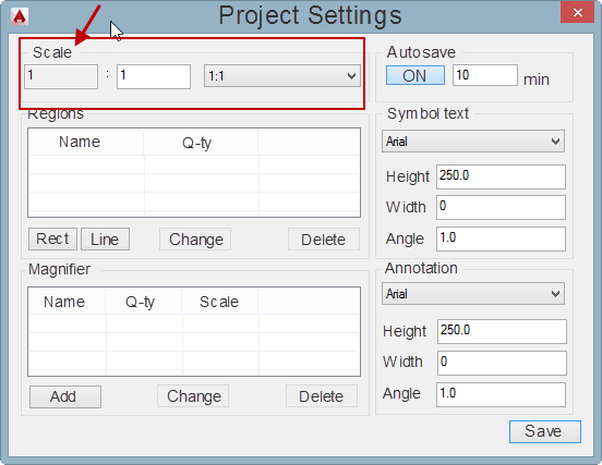
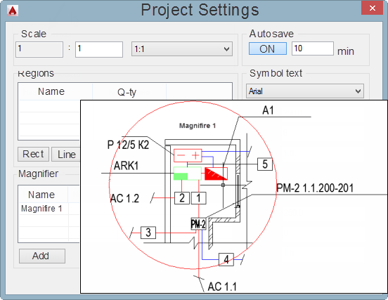
Project settings - Scale
The project may be started in a new blank sheet or in an existing drawing with the building plan.
During the first stage, it's very important to set drawing scale of the building CORRECTLY.
The scale is set in millimeters. If the actual length of the room is 3000 mm (3 m) and length on the drawing is 3000 units, the scale is 1:1.
If the actual length of the room 3000 mm (3 m) and length on the drawing is 30 units, so it means scale is 1:100, i.e. 100 times smaller than in reality.

Drawing Scale
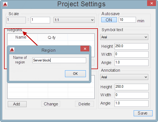
Project settings - Regions
If you need to make BOM (specifications) for separate parts of your project - for example, for one building or one floor - you can use the ‘Project Regions’ command. That command allows you to determine a part of building plan into the red rectangle on the drawing.

Project Regions
Magnifires
The magnifier tool in the project is a part of the building plan, which has to be shown in larger scale. The magnified area in the project is created in the ‘Project Settings’ windows.
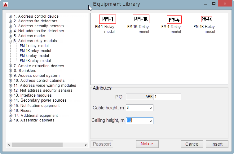
Library of Equipment
When you click the ‘RUBEZH Database’ button, the list of the available equipment types opens. Users can see a tree with equipment on the left and preview symbols on the right.
The graphic symbol is an intelligent DWG block with specified attributes. Before you insert any block of the equipment it is necessary to set the height of the equipment location, from floor to ceiling, in meters. It is necessary to automatically calculate the cable length in the project. The height of the equipment location can't be more than the ceiling height.
 in AitoCAD - DWG blocks")
Library of Equipment
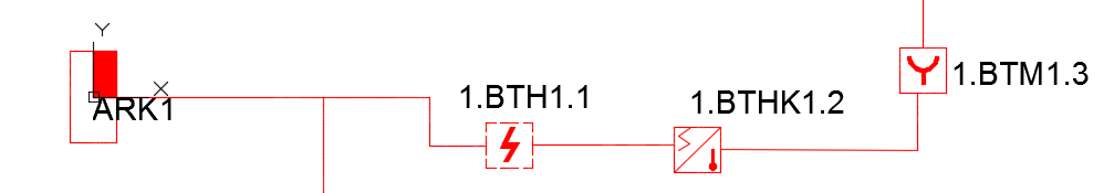
The program automatically creates and inserts the positional number for equipment (for each graphic symbol). Sequence numbers can't be repeated.
For address equipment, a positional number (PO) are created and inserted automatically as soon as the cable is connected. Therefore, at first the address equipment is inserted without a PO (positional number).


Positional Numbers for Address Equipment
Cables
In the program, there is an opportunity to draw various types of cables. Each cable type has limitations in length and other parameters.
Address Cable has a position number written as ALSx.y, where ‘X’ is the number of the main control device and ‘Y’ is the index number of the cable. Numbers X and Y are received automatically when the cable is connected to the main control device.
The address cable is limited to a length of 1,000 meters. The program gives its first warning when the cable length is more than 900 m. When cable length is more than of 1,000 meters, the program does not allow users to draw the cable.
Interface Cable has a position number written as RSх, where ‘X’ - index number of the Interface cable issued by the program automatically.
The interface cable is limited to a length of 1,000 meters. The program gives its first warning when the cable length is more than 900 m. When the cable length is more than 1,000 m, program does not allow users to draw the cable.
For other cables (ex. power cables), the position number is set manually by the user, but there is a verification of position numbers.
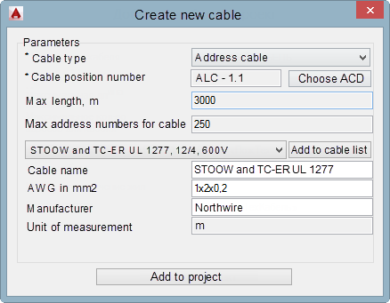
New cables in the project
To create a new cable, users must click the 'New cable' button. The Line (Polyline) may contain a single cable or a group of cables, so you can draw routes. Before you start drawing a cable line, you need to add the cable to the project.

Add a New Cable to the Project
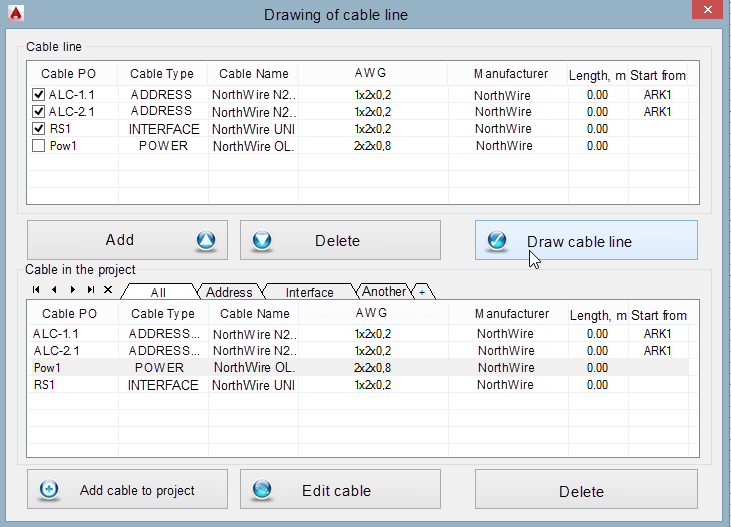
User may draw a line (polyline) which contains a single cable or many cables, i.e. the route. For selecting necessary cables use the checkboxes. Next, click 'Draw the cable line'.

Draw the Cable Line in AutoCAD
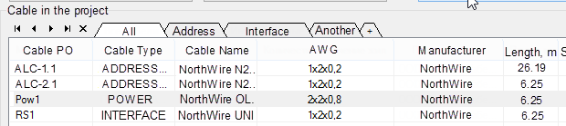
If the cable is not applicable for the equipment (graphic symbol), the program issues a warning. For example, the interface cable can't be connected to the fire detectors, so the program issues the warning: ‘Inapplicable equipment’. When the cable line is drawn, user may see the length of the cable in meters in the ‘Cable in the Project’ window. Cable length is calculated automatically and length depends on the project scale in the Settings.

Cable Length
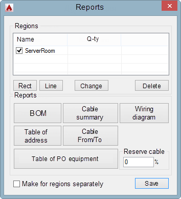
Reports
You can create reports at any time. There are such reports as a Bill of Material Components, Cable Summary, Cable From/To, and List of Components. Before issuing a report, the program checks project for errors.

Reports
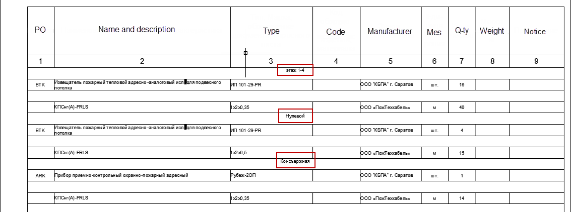
BOM (specification)
Users can select areas they want to create a report for. If there are no areas in the project, a report will be created for the entire project. Users can make areas in the project by using special buttons in the Project Settings window.

BOM in AutoCAD
Cable From/To and Cable Summary
Cable Summary is a report where we can see the length of all cables in the entire project. All cables are grouped by manufacturers and names.
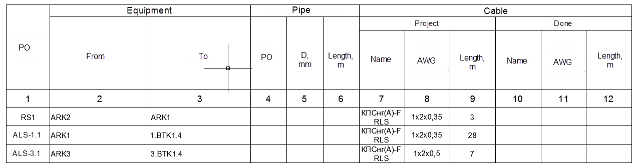
Cable From/To is a report where we can see short cable segments from one device (ex.graphic symbol, DWG block) to another device (ex. graphic symbol, DWG block). For each cable segment with a defined length.

Report - Cable From/To
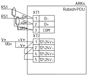
Wiring diagram
Users can insert Wiring diagram for equipment used in the project.

Wiring Diagram